
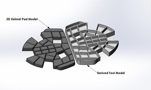
Therefore, our engineering team would have to reverse engineer the part design. Although this was a bit more CAD work, it was necessary in order for us to design the tooling that would allow us to compression mold an identical part.
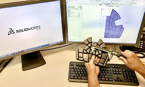
This process was made much simpler as we use Solidworks™ for our CAD design. Fortunately, the pad was symmetrical from left to right, so we only had to plot and dimension one-half of the part. Our CAD software allowed one of our engineers to then mirror the part geometry of the opposite side of the part.
Once the part geometry was designed two-dimensionally, our CAD expert was able to use the extrude function of Solidworks™ to create the required depth of the part and then a 3D model. When the part design was finalized, we sent a dimensioned part drawing and a 3D CAD model of the part to our customer. They reviewed both and agreed that we had succeeded in the reverse engineering of the part geometry. We were asked to formally quote piece prices and the associated prototype and production tooling costs.
More complex matched tools can also require machined and hardened A2 steel plates to serve as a surface to cut against. In this case, only machined aluminum tool cavities would be required to mold this part.
In this particular case, our customer simply told us which materials had been used to mold this part in the past and we chose a very similar material from the foams that we already stock.
Our R & D engineers then set the tool up in one of our hydraulic presses and used the tool to compression mold prototype parts. The parts were sent to our customer for evaluation and approval. The customer was very pleased with the part aesthetics and more importantly the fit and function of the helmet.
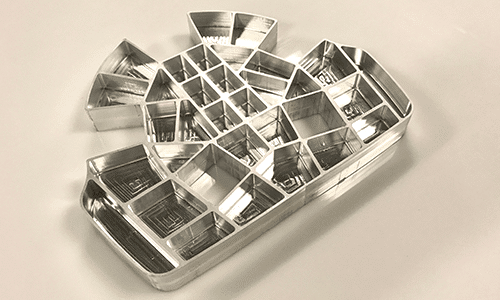
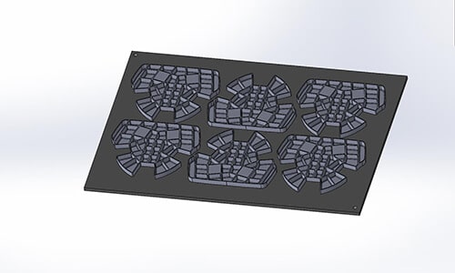
We then proceeded to build a multi-cavity production tool. This required that we have several more tool cavities machined out of 6061 aluminum. When the additional cavities were complete, the expert craftsmen in our tool shop assembled them into our proprietary tool base. Our R&D team used the new production tool to compression mold the first article parts for customer approval. The first article parts were approved by our customer soon thereafter.
You can observe the machining process of the prototype tool in this video.
We then built the production tooling for this pad and have been manufacturing these pads for several years. Since then, this customer has had us develop other molded foam hockey helmet pads for their product line. The relationship has developed into a mutually successful partnership and we look forward to continued growth with this customer.
Please contact Flextech if you have an idea for a new product you would like to develop, or a problem you would like our sales and engineering experts to help you solve. We look forward to an opportunity to work with you.

